
Add a real knocker to your Cactus Canyon pinball machine
As the last WPC pinball machine made (the next games were Pinball 2000), Cactus Canyon does not have a real knocker installed.
Williams started to reduce costs, therefor their latest models do not have a real knocker coil installed.
Instead they make use of a similated knocker: just the sound is played through the speakers.
Unfortunately the sound is a little weak and does not really compare to the hard knock a real knocker coil makes.
While the wiring is not present in the cabinet, the games software does make use of it. The knocker coil still shows up in the solenoid test (T.4) as coil number 7, but is indicated as unused. This isn't completely true - what they really mean is that it's not installed. The transistors that drive this coil are activated during the game. So nothing limits us to wiring a real coil into the machine.
Adding a knocker coil is very simple to do. Actually it's one of the quickest modifications I have ever done to a pinball machine, everything together (even looking up things in the schematics) it took me less than 15 minutes.
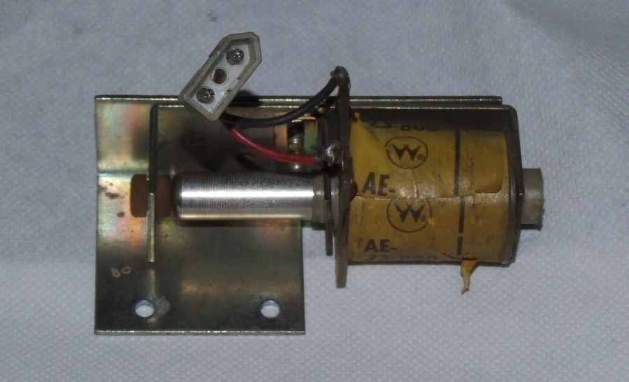
First thing we need is a knocker assembly. Luckily I still have a few laying around from games I have parted out.
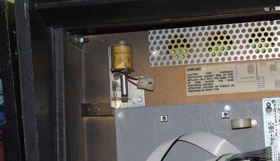
First install this assembly in the backbox. On WPC95 machines it goes on the top left. Secure it with three screws.
I don't have a picture of the molex connector that connects to it. You need a matching female molex connector (3 pins) and solder
two wires to it (outer pins, middle pin is not used on the default knocker coil connector).
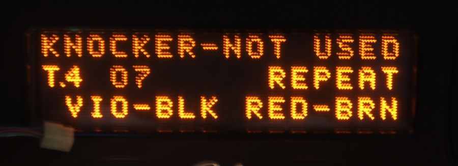
Now we need to find out how and where to connect the wires. Go into the self tests and start the solenoid test (T.4).
Coil 7 is the knocker coil.
The coil and its associated transistors
and what connector pins it uses, is not mentioned in the solenoid table in the manual.
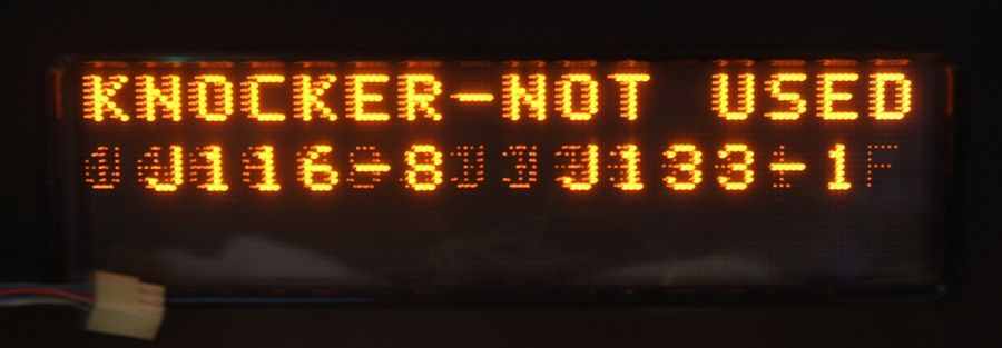
We find this out by pushing
the start button in the solenoid test. This will show us extra screens, one of them list the information we need:
this coil is connected by J116 pin 8 and J133 pin 1.
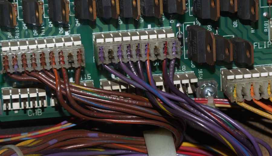
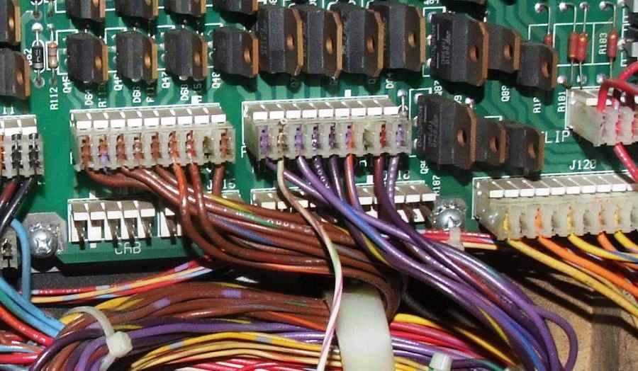
Here's connector J116 (purple wires). It's at the bottom of the powerdriver board.
Remember connector pins are numbered
clockwise, to connectors at the bottom of the board have pin 1 on the right.
Hooking up the coil is easy -
push one of the wires of the knocker coil into the IDC connector at pin 8. As there is no diode on the coil it does not
matter which of both wires you use. I don't have an IDC connector tool, so using a flatheaded screwdriver I carefully
push the wire in place.
Now we need to hook up the second wire. Will it also be this simple ?
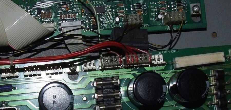
Here's connector J133. It's at the top of the board, so pin 1 is on the left. Here we have a problem: there is already
a red wire at pin 1, which provides power to coils below the playfield.
I do not want to hack my original wiring.
I do not want to cut this red wire and splice it to add our new wire.
Other WPC games have the knocker solenoid connected
to the playfield wiring, power from the backbox (connectors on the pcb) goes to the playfield coils, and from there one wire goes
back up into the cabinet to the knocker coil. If you want to connect the knocker coil and want it to look really original,
this is the way to do it. But as I want to keep this modification as simple as possible. I don't want to search around
below the playfield and add long wires, so I look for an alternative.
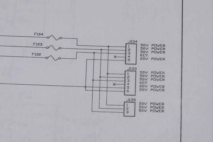
Time to take out the WPC-95 schematics and search for another source of 50 volts for the solenoids.
We find 50v not only on J133, but also on J134 and J135.
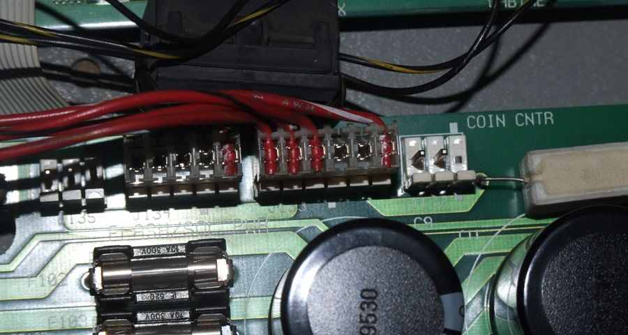
On Cactus Canyon J135 is not used, on J134 is a connector plugger in with one wire taking 20 volts.
One option is to take a new connector and plug it in J135. I decide to use the existing J134 connector.
Disadvantage of running two wires this way is that they're not completely integrated with the existing wire loom.
If I ever want to remove the playfield out of my machine (which I don't plan to) I have to be careful with these wires.
if you really care about this, use an extra connector for J135 (and label it) and connect the other wire using zip-ties
to the existing wiring loom.
Here is the extra wire added to J134. Now the knocker solenoid is wired up !
Time to go into the solenoid test, and yes! the knocker coil is activated !
As you can see this modification is easy to do. The only difficult part is that you need to push the wires into the IDC connectors (for this you can buy a special tool). It doesn't add a lot to gameplay (you just hear a real knocker when you get a replay/high score/..) but it's nice to add it and make your Cactus Canyon pinball machine complete.